 Home >
Corporate News >
Designing a Crushing & Screening Plant – Part II. Secondary Cone Crushing Stage
 2020.11.05
The purpose of the primary stage was mainly to crush the stone into conveyable size and thereby make it possible to further process the rock in a continuous process. The secondary stage is the first part of this process so from here on and downwards the crushing and screening plant should be continuously operated.
When we now look closer at the design of the secondary stage, we can start by defining the purpose. It is basically two folds: Production of coarse products and produce material suitable for further crushing. If the quality demands on the finer products are low, it is also possible to produce them in the secondary stage.
Before moving into the design of the secondary stage there is one very important part between the primary stage and secondary stage that should be mentioned. Since we are now aiming to design a process that is running continuously the intermittent operation of the primary stage cannot be allowed to transfer to the secondary stage. This is done by using a stockpile or other major storage facility in between the two stages.
A large intermediate stockpile will also secure operation of the plant if any major problems occurs with any of the equipment supplying material to the plant or if the operation in the pit must be stopped due to blasting. To have enough material in the intermediate storage to supply the plant for at least a couple of hours is therefore a good practice.
One of the first thing that should be addressed when designing a cone crusher stage is how to handle smaller fractions and fines. If the material from the primary stage contains fines it is advisable to remove that before the cone crusher. For secondary gyratory crusher fines could be acceptable but there are no benefits of sending it through a crusher. Same thing with smaller fractions, if these fractions will be extracted as product or crushed in the tertiary stage there are no benefits of sending them through the secondary crusher.
For the secondary stage both a conventional cone crusher and a secondary gyratory crusher could be utilized, which one to select mainly comes down to the needed capacity and material feed size. For applications with large feed size and relatively low capacity requirement the secondary gyratory crusher should be used, see Figure 1.
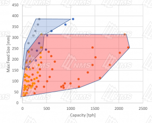
Figure 1. Application area for Cone Crusher (red) and Secondary Gyratory Crushers (blue).
As seen in the figure there is an overlap between the two types of crusher but in the overlap area the secondary gyratory crusher is the most cost-efficient selection. In the overlap area the cone crushers are big and operated with a small eccentric throw while the secondary gyratory crushers are smaller and operated with larger throws, hence the secondary gyratory will provide the same capacity with a smaller investment.
Another aspect of crusher selection is material shape. This paper will not go into detail about the cone crusher crushing chamber, but the type of crusher selected in the secondary application will affect the quality of the crushed material. A conventional cone crusher will normally produce material of better shape than a secondary gyratory crusher. So, if shape is a priority the selection becomes trickier and more attention to the primary stage is often needed to increase reduction. The CSS of the primary jaw crusher becomes crucial in order to make the feed for the secondary cone crusher small enough to fit, this is seldom a problem with the secondary gyratory crusher.
When selecting the secondary crusher, the strategy is basically the same regardless of the type of crusher. As with the jaw crusher it is good to select the crusher with some capacity margins. The main reason for this is that the material coming from the primary stage might still vary over time and that the crusher capacity can vary as a result of chamber wear. It has been found that this effect is often most noticeable on a secondary gyratory. Some margins on capacity is therefore also best practice in the secondary stage. Without margin it could be that the secondary crusher becomes the plant bottle neck and this will cause problem in the downstream process. When operating a crushing plant the best location of the bottle neck crusher is the final crushing stage, to ensure that this happens excess capacity in the secondary stage is a good design rule. The rule of thumb is to design the secondary cone crusher with approximately 90% capacity utilization and the secondary gyratory crusher with 80%-90% capacity utilization.
For crushing stage process layout, the question of open or closed circuit are often discussed. Since this is valid for secondary and later process steps this paper will not go into depths of pros and cons of different options but instead please refer to our paper on the topic on crushing process design.
As mentioned in the paper about primary stage design there is often no point in doing the final design and equipment configuration of the primary stage before it is connected to a secondary stage. So, what are the main objectives when the two stages are combined?
What we want to achieve for the primary stage is to produce a material suitable for the secondary crusher but at the same time, we do not want to push the primary stage harder than necessary.
What is important to achieve is enough reduction in the primary stage so that the secondary crusher can accept the material. It is advisable to allow for some margin on feed size when it comes to the secondary stage configuration. Plan for the event that the material coming from the primary stage is slightly coarser.
In the secondary stage it is often required to produce coarser products. If the quality requirements allow it is also possible to produce finer product in this stage but one should be aware of that for example particle shape will not be good. It is also difficult to do anything to control the amount of material produced or to do anything to improve the shape. But if this is not an issue there is no reason to avoid extracting these fractions in the secondary stage. One could also select to keep these products in separate storages and then produce the same fractions with higher quality in the final stage.
What can be produced with high quality is coarser fractions like railway ballast, often 32-63 mm or 30-50 mm. In order to reach the high shape demands placed on railway ballast it is important to only use material crushed by the secondary crusher and to use a cone crusher. It is not impossible to produce railway ballast in a secondary gyratory but if it fails it is often hard to address this without major changes, maybe even replacing the crusher.
It is common that the production of railway ballast is only done when there is a direct need, at other times the material needs to be further crushed into other products. This introduces the question, how should the process with optional crushing of the railway ballast be designed? It is apparent that there are two main options on how to process the railway ballast surplus: It can be re-crushed in the secondary crusher (Figure 2) or sent to the tertiary crusher (Figure 3).
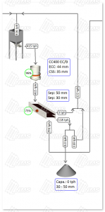
Figure 2. Secondary stage with optional re-crushing of railway ballast
The option to re-crush the railway ballast will in both cases requires the receiving crusher to have additional capacity. One aspect to consider is feed size. Depending on the tertiary crusher it could be that the railway ballast will require a coarser chamber to be selected. If railway ballast is extracted from the process this will mean that the tertiary crusher is equipped with a coarser chamber than necessary. In this case it should be evaluated if there is a risk that problems such as limited min CSS or localized wear in the bottom part of the chamber can arise. Keep in mind that it is beneficial to have the possibility to freely optimize CSS for best production and material shape. This is described in more detail in the paper about crushing chamber selection.
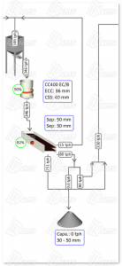
Figure 3 Secondary stage with optional mix-in of railway ballast in feed to tertiary stage.
If you would like to study the impact when changing from 100% railway ballast production to 0% railway ballast production the full flowsheets from Figure 2 and Figure 3 is available in the Appendix (Figure 4, Figure 5, Figure 6, and Figure 7).
This paper has addressed the main challenges and considerations of the design of the secondary crushing stage. This is the first part of the plant where we can talk about a continuous process and where products of quality can be produced. In the case of railway ballast production, it is possible to do this efficiently and with the required quality if the process is correctly designed. This is also the first stage where the production can be altered for different production goals. With a well thought through design it is possible to be efficient in different production scenarios. As you probably have noted the design of the process will heavily depend on the utilization of a process simulation software. It is often essential to have this type of software to evaluate different options and thereby find the best solution.
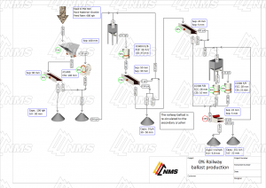
Figure 4. Process with railway ballast (30-50 mm) being re-crushed in the secondary stage. Here all 30-50 mm is re-crushed

Figure 5 Process with railway ballast (30-50 mm) being re-crushed in the secondary stage. Here all 30-50 mm is sent to the stockpile.
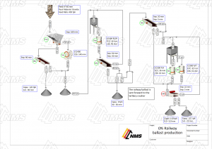
Figure 6. Process with railway ballast (30-50 mm) being crushed in the tertiary stage. Here all 30-50 mm is crushed.
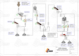
Figure 7. Process with railway ballast (30-50 mm) being crushed in the tertiary stage. Here all 30-50 mm is sent to the stockpile.
